Project Status: Discontinued
Project Started: Fall 2005
1. Introduction
I did not originally think of this idea but have done a great deal of research on the operation and components in the first generation 1990’s (93-99) Cadillac northstar ignition setup. I have put together a lot of useful information for anyone looking to complete this project or modify the Northstar DIS setup for use on there car. These pages outline some of the needed information to run a Cadillac northstar DIS (distributorless ignition system) ignition module and coils on a SBC with almost any GM OBD-I HEI ECM \ ECU. I planed to use this on a 1227730 90-92 f-body or 1227727 90-91 C4 Y-body speed density ECM.
The Cadillac northstar first generation ignition system was used on the following vehicles:
| Brand | Vehicle | Year |
| CADILLAC | ALLANTE | 1993 |
| CADILLAC | DEVILLE | 1996 – 1999 |
| CADILLAC | DEVILLE CONCOURS | 1994 – 1999 |
| CADILLAC | DEVILLE DELEGANCE | 1997 |
| CADILLAC | ELDORADO | 1994 – 1999 |
| CADILLAC | ELDORADO ETC | 1998 |
| CADILLAC | ELDORADO SPORT | 1993 |
| CADILLAC | ELDORADO TOURING | 1993 – 1997 |
| CADILLAC | SEVILLE | 1999 |
| CADILLAC | SEVILLE SLS | 1994 – 1998 |
| CADILLAC | SEVILLE STS | 1993 – 1998 |
| OLDSMOBILE | AURORA | 1995 – 1999 |
2. Cadillac Northstar DIS Theory & Operation
2.1) Overview
The Cadillac Northstar ignition system on a factory 1993-1999 Northstar engine is composed of an ignition module, four coils, a crankshaft trigger wheel, two variable reluctance crankshaft position sensors, and a cam sensor used for SFI operation by the PCM. The two crankshaft position sensors are used to quickly determine crankshaft position for fast engine starting, know as “Fast-Start”. Using two crankshaft sensors allows the ignition module to determine the engine position within 180 degrees of rotation of the crankshaft. Another benefit of two crankshaft sensors is redundancy; in case one sensor fails, the module can operate off the remaining working sensors. If you are running two crank sensors and a cam sensor any one sensor can fail, including one of the crank sensors and the module will continue to operate. If you operate the module without a cam sensor both crank sensors are needed to maintain operation.
2.2) Crankshaft Trigger Wheel (reluctor ring)
The Northstar crankshaft has a trigger wheel (also called a reluctor ring) cast into the crankshaft between #3 and #4 main bearings. Two crankshaft position sensors are installed into the side of the engine block (facing front of car in FWD applications) between cylinders 4 and 6. The trigger wheel has 32 notches, 16 large raised areas, and 16 small raised areas, as seen in Figure 1 and 2 below.
Figure 1: GM drawing of Northstar trigger wheel
Image from GM, Cadillac division.
Figure 2: Cadillac Northstar crank trigger wheel put into CAD
Note: Drawing not to scale, for accurate scaled version download the the CAD or PDF drawing below.
Each notch and small raised area is 1/3 the size of the large raised area. In the GM drawing of the Northstart in Figure 1 you can see that they blacked out the notches between the small raised areas to create 24 even notches and large raised areas. This is why GM considers this a 24x trigger wheel. The eight uneven notches are used by the ignition module to determine crankshaft position to determine which cylinder is next in the firing order.
2.3) Northstar PCM & ICM wiring
Note: The firing order above is that of a GM northstar block and must be changed for SBC applications, see below
2.4) Crankshaft Position sensors
The two crankshaft position sensors used in the Northstar setup are variable reluctance sensors separated 27 degrees apart. Each sensor is mounted within a tight tolerance of the trigger wheel (reluctor wheel), 0.05″ (1.3mm) on the factory engine.
2.5) Camshaft Position sensors
A camshaft position sensor is not needed on HEI ECM conversions because they are bank fire applications this is only needed for SFI PCM’s.
The camshaft position sensor is positioned over a dowel pin located on the exhaust camshaft cam gear. One Off-On-Off signal pulse is created every camshaft rotation and every two crankshaft rotations.
2.6) Coils
The four coils used in the Northstar setup employ a waste spark firing method. Waste spark firing means that two spark plugs are fired at one time thus lowering the number of coils needed and the cost. When a coil fires of the two cylinders fired, one is on the compression stroke and one is on the exhaust stroke.
2.7) Ignition Control Module
The Northstar ignition control module is what processes the input from three sensors and the proper signal output to the ECM \ ECU \ PCM.
It performs the following functions and more:
– It monitors the On-Off pulses produced by the two crankshaft and one camshaft position sensors.
– It creates a 4X and 24X reference signal (4X REF HI and 24X Crank) sent to the PCM for ignition control.
– It creates a camshaft reference signal (CAM HI) sent to the PCM for fuel injection control.
– It provides a ground reference (REF LO, CAM LO) to the PCM.
– It provides a means for the PCM to control spark advance (BYPASS and IGNITION CONTROL) called IGNITION CONTROL MODE.
– It provides a limited means of controlling spark advance without PCM input called MODULE MODE.
– The IC module is not repairable. When a module is replaced the remaining components must be transferred to the new module.
2.8) Ignition Synchronization
| Ignition Control Module signal description | |||
| Single | Signal Name | Voltage Range | Description |
| A | Crankshaft position sensor ‘A’ | +/- 100V AC | Voltage and frequency vary with engine speed |
| B | Crankshaft position sensor ‘B’ | +/- 100V AC | Voltage and frequency vary with engine speed. Signal lags crankshaft position sensor ‘A’ by 27 degrees |
| C | Camshaft position sensor | +/- 100V AC | Voltage and frequency vary with engine speedThis signal occurs every two crankshaft revolutions |
| D | 4X Ref Hi | 0 – 5V DC | Key on, Engine Off: Signal is high. High to low occurs at first sync, then follows firing order. |
| E | Bypass | 0 – 5V DC | Key on, Engine Off: Signal is low. Low to High occurs with PCM ignition control. |
| F | Ignition control | 0 – 5V DC | PCM sends ignition control signal to ICM. The falling edge signals ICM to turn off coil primary current. |
| G | 24X Crank | 0 – 5V DC | This signal will remain high if the ICM identifies a fault with one of its three position sensorts |
| H | 1/2x Cam Hi | 0 – 5V DC | The PCM uses this signal for sequential (SFI) fuel control |
| I | Ground Ref. | 0V DC | This is the ground reference between the PCM and ICM |
1) The crankshaft reluctor ring has 24 evenly spaced notches plus eight additional notches (shaded) used for synchronization for a total of 32 notches.
2) As the crankshaft rotates, the notches pass the position sensors and create a voltage pulse signal in the sensor that is an input for the ignition control module (ICM).
3) Because of the physical location of the 2 crankshaft position sensors, the signal of B lags the signal of A by 27 degrees of crankshaft revolution.
4) To synchronize the ignition, the ICM first counts the number of B pulses between every 2 A pulses. There can be 0, 1, or 2 B pulses between A pulses.
5) When the ICM sees 0 B pulses between A pulses , it starts counting B pulses between A pulses. When the ICM counts exactly 4, it synchronizes the ignition on the very next A pulse. If the ICM counts over 4 (jumps from 3 to 5), it waits for another B pulse between A pulse to start counting again.
6) This process allows the ignition to synchronize and fire the first spark plug within 180 degrees (1/2 engine revolution).
7) The camshaft position (CMP) sensor provides the ICM with cylinder #1 firing order information, which the PCM uses for sequential fuel injection.
8) Using 3 sensors allows the ICM to maintain ignition synchronization even if one of the 3 sensors fails.
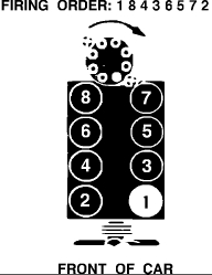
2.9) Firing Order:
To run the northstar ignition module on a SBC you will connect the wires to the coils as follows.
1’st Gen Northstar Firing order
1-2-7-3-4-5-6-8
1’st Gen SBC Firing Order:
1-8-4-3-6-5-7-2 looking at the front of the motor counting back: driver side (right) = 1-3-5-7 pass side (left) = 2-4-6-8
2.10) Ignition Control Module Pinouts:
I have created a column in the tables below to outline which pins would be used if using the northstar ignition module on a 1227730, 1227727, or pretty much any HEI distributor OBD-I GM car.
| Connector 1 – Crankshaft Sensors | ||
| Pin | Used on HEI ECM | Function |
| A | Yes | Crankshaft sensor A high signal |
| B | Yes | Crankshaft sensor A low signal |
| C | No | Not Used |
| D | No | Not Used |
| E | No | Crankshaft sensor B low signal |
| F | No | Crankshaft sensor B high signal |
| Connector 2 – Power and Tachometer output | ||
| Pin | Used on HEI ECM | Function |
| A | Yes | Ground |
| B | Yes | Tachometer signal output |
| C | Yes | Ignition controlled battery voltage |
| Connector 3 – Cam sensor | ||
| Pin | Used on HEI ECM | Function |
| A | No | Camshaft sensor high output |
| B | No | Camshaft sensor low output |
| C | No | Not Used |
| Connector 4 – PCM \ ECM Output | ||
| Pin | Used on HEI ECM | Function |
| A | No | 24x spark reference signal |
| B | No | 1/2x cam signal |
| C | Yes | 4x fuel control signal |
| D | Yes | Ignition bypass |
| E | Yes | Ignition control |
| F | Yes | Ignition reference low |
3. Trigger Wheel Design & Fabrication
3.1) Crankshaft Trigger Wheel
I purchased a used Northstar crankshaft off eBay to get the measurements of the trigger wheel and create the wheel in CAD. Here are the measurements of the Northstar trigger wheel:
Most measurements taken from the trigger wheel are giving in a range because measurements taken at different points of the wheel yielded different results, this is due to machining tolerances of the wheel. The tolerances of the wheel do not need to be very close, the notch position and size is what is important so the module can figure out where the engine is in rotation. Each of the 32 notches on the crank trigger wheel is about 15/64 (or 0.235 to be exact) of an inch in length and 3/16 – 13/64 of a inch deep. There are 16 small raised areas which are about the same length as the notches, they are about 7/32 (0.21 – 0.215) of a inch. There are 16 large raised areas which are about 3 times the length of the notches and measure in at 0.66 – 0.665 of a inch. So calculating in a percent of error for machining tolerances, each notch and small raised area are the same length. The large raised area is three times the length of the notches.
The above broken down into degrees:
– 32 notches 3.75 degrees in length
– 16 small raised areas 3.75 degrees in length
– 16 large raised areas 11.25 degrees in length
The thickness of the trigger wheel is 9/32 – 5/16 of a inch thick, the thickness is different at different points around the wheel due to the fact that one side of the wheel is un-machined cast and the other is machined flat.. The diameter of the trigger wheel is about 6 & 15/16 inches.
3.2) Northstar Crankshaft Trigger Wheel CAD
Here is the AutoCAD file of the Northstar trigger wheel, this can be scaled in size as needed:
Northstar trigger wheel (AutoCAD File)
Northstar trigger wheel (PDF File, only for viewing purposes)
Page created: January 2006
Page content last updated: 06-13-2009
Great Information. I am thinking about using this ignition arrangement on a 500 Cadillac engine with an original EFI manifold and throttle body with adapted TPS and IAC. This package would all be controlled by a speed density 1227730 ECM modified by Dynamic EFI with embedded lockers. The engine would be installed in my 1978 GMC Motorhome. John
Think you could set up a system to run an LT-5 ZR-1???
how does this ring allign with tdc when mounting?
ok notch #1 lines up with sensor A with crank at tdc. now you dont have to search for hours like i did :p
your welcome! lol
with more readin i see that sensor A actually should line up with notch 24 :s
sorry for my pre-ejaculation i was excited lol
got a weird thing going on with the crankshaft sensors (’97 sls): connect one of them and it fires up, connect both of them and it won’t. one is a new “wells” from autozone the other one a known good, used ac delco. resistance is the same on both (1.4kOhm), cranking the new one puts out 2.5V AC, with the used one 8.5V AC. is there a possibility that the voltage difference causes a no-start situation? as said, individually both sensors work, connected whichever way…
I am having same problem. Did you find out anything?
thank you,
Marty
Im having the same problem how did you solve it?
How did you solve it? im hvaing the same issue
In April I paid Penske Cadillac, in Torrance CA, to remove and replace my 1996 Eldorado’s North Star engine, with a new one. This the dealer did. Since then, like a string of Christmas tree lights shorting, every 300 miles of use or so, I have been forced to purchase, three sequential times, ignition system componets, because the engine light keeps coming on with “ignition system.” The last time, a GM home office technican instructed the dealer “move around some wires” which the dealer did, without charge and sent me on my way, with the statement, “the next time you will have to replace the “wiring tree.” Do you think the dealer failed to combine the engine and the system, or that the old system is known not to work with a 96 engine?
Thanks much for your opinion
JOe Ryan
Excuse me, the last sentence should be “new” engine, not 96 engine
On a different subject that I think you might be able to help with, do you know if a 1997 Eldorado camshaft is interchangeable with a 1999 Seville STS? Both are “Y” vin.
I am going crazy trying to locate the correct part (the camshaft that runs the water pump)
thanks for your help!
Luke, Great information! I’m in the process of adapting the Northstar module to a twin turbo changed 383 LT1 engine going into a 2nd gen Camaro. I have machined the reluctor wheel to your specs for mounting on the back side of the vibration dampner. I realize this is some 8 yrs old, but I have specific questions concerning the syncronization process of the module (probably not enough room to explaing here). If you would, please contact me at the supplied email. Your help would be greatly appreciated. Thanks, Rod
I am also adapting the northstar setup to a lt1 engine, mine is 97. I would be very grateful if you could share what you know about it.
thanks, tony.
did you get it sorted?
Hi There,just wondering if you can tell me the exact location of the 2 crank sensors on a 1997 cadillac seville sts
I replaced both crankshaft sensors a & b but the car will only run with one sensor plugged in and it doesn’t mater what sensor is plugged in or with plug I use. Can anybody help me?
How did you solve the problem?
It is a 1997 Cadillac sts ^^^^^^
I have a 94 cadillac that was diagnosed as an ecu problem. Its runs wide open and the instrument panel and heat wont come on. Is the ecu the culprit or is something else wrong?
This information is by far the best I was look in at this since I have a camshaft code with misfire #1 I installed new camshaft sensor and still get the code I have a 1998 seville sls can anyone give me so words of wisdom please
http://www.thirdgen.org/forums/diy-prom/193531-do-away-dizzy.html
incase anyone needs it. this thread starts in 2003 and ends with a running car in 2009. should answer just about any questions you might have about the N* mkd
There was not ground going to the camshaft plug ran a ground wire and cleared code never came back
have a 1997 cad deville 4.6 with no reading coming out of the camshaft sensor or wiring. why is there no reading? Wiring is good. How do I repair this. Sensor is good.
I replace the top sensor .it keeps blowing it…what could cause this..i home it be for I put it on then when I turn the key switch it doesn’t home no more
Replace three already
The biggest problem with these systems is the ignition control module is no longer available. So you have to take your chances with a over $200 one on eBay that’s used and just hope it works.
i have a 2000 model seville sts and the coil packs in the valve cover and i wish to move my coils back up top like previous yrs is this possible since amazom told me they would fit im stuck with them and my haynes man doesnt have a schematic for the ign module
Hi I am having and hi reference signal code po41 ,. I don’t know what camshaft sensor to test. I have and cadillac deville concours 1995 4.6 engine eng code y